Object Shape Examples (Track File Format)
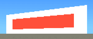
The following is an example of an ad billboard in the Phoenix track.
From one side:
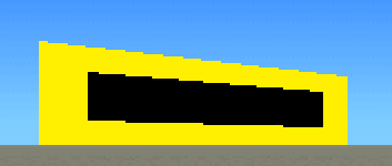
And the other side:
The total length of the data that describes this object is 402 bytes.
Initial Data
| Hex | Dec | Description |
|---|---|---|
| 00 06 | 1536 | Header |
| 04 27 | 9988 | Offset to scale values |
| F5 15 | 5621 | Header "2" |
| 08 27 | 9992 | Offset to graphical elements |
| F5 15 | 5621 | Header "3" |
| 23 27 | 10019 | Offset to point data |
| F5 15 | 5621 | Header "4" |
| 63 27 | 10083 | Offset to vector data |
| F5 15 | 5621 | Header "5" |
|
00 00 00 00 FF 7F 00 E0 0D 00 |
Unknown data | |
| 75 27 | 10101 | Offset to graphical element data |
| F5 15 | 5621 | Header "6" |
Since the scale value offset points to the location we have now reached, there is no additional 10 bytes of unknown data, which occurs in a few objects on some tracks.
Scale Values
| Hex | Dec | Description |
|---|---|---|
| 00 06 | 1536 | Scale value |
| A0 04 | 1184 | Scale value |
Graphical Elements
| Hex | Description |
|---|---|
| 00 01 | Header |
| FF | End of header |
| 08 | Base color of polygon 1 (white, but can be affected by "Unknown" value in an object setting) |
| 02 03 FC FF | Points in polygon 1 (signed bytes) |
| 00 | End of polygon 1 |
| 09 | Base color of polygon 2 (red, but can be affected by "Unknown" value in an object setting) |
| 05 06 F8 F9 | Points in polygon 2 (signed bytes) |
| 00 | End of polygon 2 |
| 00 | Base color of polygon 3 (black, but can be affected by "Unknown" value in an object setting) |
| 07 08 FA FB | Points in polygon 3 (signed bytes) |
| 00 | End of polygon 3 |
| 03 | Base color of polygon 4 (yellow, but can be affected by "Unknown" value in an object setting) |
| 04 FD FE 01 | Points in polygon 4 (signed bytes) |
| 00 | End of polygon 4 |
On one side of the ad billboard, polygon 1 is the large white area, which has polygon 2, the smaller red bar, inside it.
On the other side of the ad billboard, polygon 4 is the large yellow area, which has polygon 3, the smaller black bar, inside it.
The parsed data reads like this:
| Color | Vectors |
|---|---|
| 8 | 2, 3, -4, -1 |
| 9 | 5, 6, -8, -7 |
| 0 | 7, 8, -6, -5 |
| 3 | 4, -3, -2, 1 |
Where each number is a vector, and a negative value means that the vector is reversed. If reversed, it means that what is normally the start point is now the end point, and vice versa.
Points
| Hex | Description |
|---|---|
| 00 00 22 00 00 00 00 00 | Point 1 |
| 00 00 02 00 00 00 00 00 | Point 2 |
| 00 80 00 00 00 03 00 00 | Point 3 |
| 01 80 00 00 00 03 00 00 | Point 4 |
| 00 00 24 00 C0 00 00 00 | Point 5 |
| 04 80 00 00 40 02 00 00 | Point 6 |
| 00 00 04 00 C0 00 00 00 | Point 7 |
| 06 80 00 00 40 02 00 00 | Point 8 |
The point data will be explained further soon
This calculates to:
| Index | X | Y | Z | Type |
|---|---|---|---|---|
| 0 | 0 | -1536 | 0 | Scale |
| 1 | 0 | 1536 | 0 | Scale |
| 2 | 0 | -1536 | 768 | Reference |
| 3 | 0 | 1536 | 768 | Reference |
| 4 | 0 | -1184 | 192 | Scale |
| 5 | 0 | -1184 | 576 | Reference |
| 6 | 0 | 1184 | 192 | Scale |
| 7 | 0 | 1184 | 576 | Reference |
Vectors
| Hex | Description |
|---|---|
| 00 00 | Always starts with 00 00 |
| 00 01 | Vector from points 0 to 1 |
| 00 02 | Vector from points 0 to 2 |
| 02 03 | Vector from points 2 to 3 |
| 01 03 | Vector from points 1 to 3 |
| 04 05 | Vector from points 4 to 5 |
| 05 07 | Vector from points 5 to 7 |
| 04 06 | Vector from points 4 to 6 |
| 06 07 | Vector from points 6 to 7 |
Graphical Elements List
| Hex | Description |
|---|---|
|
08 00 08 00 0E 00 0E 00 00 00 06 00 00 80 12 00 0C 00 00 80 |
Unknown (so far) |
Putting it all together
Since this 3D object is actually very flat, we can disregard an entire axis.
Mapping out the object with its coordinates, we arrive at something looking like this:
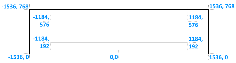
You can see the data in the Points declaration above.
NB: The 0,0 coordinate is not an actual defined point, it is just displayed in the image as a reference.
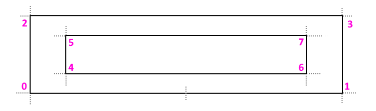
Replacing each actual point coordinate with its index (which we will need for further calculations), it now looks like this:
We will now show the vectors, as green arrows with their default direction indicated.
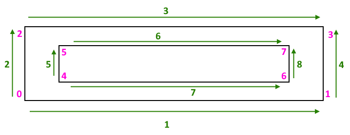
NB: The first declared vector in an F1GP object is always from point 0 to point 0, so not relevant or shown here.
As previously described, there are four polygons in the Graphical elements definitions above.
Starting with the first polygon, it is defined by the following vector declaration:
2, 3, -4, -1
This means that it starts with vector 2 (point 0 to point 2), then goes along vector 3 (point 2 to point 3). After this, vector 4 is declared, but as a negative. This means that we reverse the direction of vector 4 and go from point 3 to point 1. The next vector, 1, is also negative, so we go from the end at point 1 and close the polygon at point 0.
So the polygon is made up of the following points, in order:
0 -> 2 -> 3 -> 1 -> 0
As we can see from the image above, this is the large square. The color is index 8, which - if we look in the palette - we see is the white color.
In the same way, the next polygon is the red inner bar (color 9) goes along vector 7 and 8 (points 4 to 6 to 7), then vector 6 in reverse (i.e. point 7 to 5) and then vector 5 in reverse (points 5 to 4), so:
4 -> 6 -> 7 -> 5 -> 4
The story repeats for the next two polygons, but pretty much all in reverse:
7, 8, -6, -5
and
4, -3, -2, 1